Generating abutment bottoms
To design the emergence profile of the abutment, the part which is below the soft tissue, you should follow this step. The soft tissue is shown transparently, so you can look through it for better design control.
Tip
To set up transparency, right-click the part you want to change, select Visual properties, and then choose the desired transparency style.
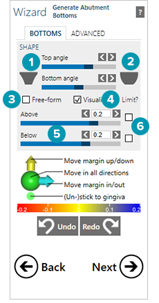
To choose a different shape, use the Shape buttons. To create a more convex shape, use the right one [1]. For a concave shape, use the button on the left [2]. Use the sliders to control the shape. With the upper slider, control the upper part of the abutment and with the lower one, control the shape of the lower part.
Free-forming abutment bottoms
Any change you make with these controls applies to all abutments that are part of the restoration. To change only one abutment, do not use the sliders, but use the free-form mode instead by selecting the Free-form [3] check box. Left-click at the place where you want to add material and material will be added there.
Removing/Adding material
To remove material, hold down [Shift] and click. To add material locally, click. To add material all around, hold down [Ctrl] and click.
Note
If you are designing a multi-unit restoration, all abutment bottoms will be adapted simultaneously. To remove material from/add material to one abutment bottom, select the abutment, activate expert mode and in the dock select Generate abutment bottoms.
Visualizing the intersection (pressure) to the soft tissue
Visualize the intersection with the soft tissue by selecting the Visualize check box [4]. In this way you can see how much pressure is applied on the soft tissue or how far the distance from the soft tissue is. Blue means there is space at the soft tissue. Red stands for pressure on the soft tissue.
Control the visualization of the soft tissue by moving the sliders [5]. This is important, because you need to very precisely control the pressure you want to apply to the soft tissue. Limit the intersection at the soft tissue by selecting the check boxes [6]. The upper check box (Above) is for distance control, the lower one (Below) is for intersection control. The distance and intersection is then controlled for all abutments by the values in the fields left from the Limit? check boxes [6]. If the values are set to zero, the emergence profile is adapted to the soft tissue scan.
Control points at the border of the abutment bottom
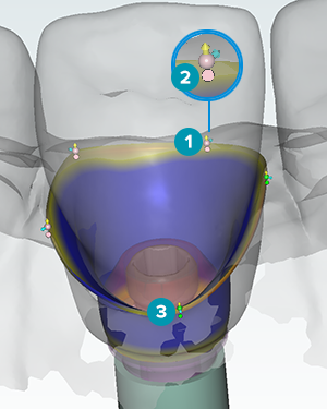
Drag these points [1] by clicking and holding the mouse button on the arrows or at the point itself. The movement is restricted by clicking on the arrows in the direction of the arrow. By clicking at the point itself the movement is free in all directions. To create a very complex shape, it is useful to add further control points.
Tip
To add a control point, click the margin of the emergence profile while holding down [Ctrl].
To remove a control point, click it, hold the left mouse button and additionally press the right mouse button.
The toggle disk - meaning of the color
Pink means that the point is attached to the soft tissue. Below each control point there is a toggle disk [2]. Use that disk to change the color of the control point. In the green mode [3], the control point is detached from the soft tissue, and you can move it away from the soft tissue completely. Set up pressure at the soft tissue by intersection.
Hold down [Ctrl] and click one of the disks to change all the control points into pink. Click again to change all the control points into green.
Advanced options
In the Height field [1], set up the height at the border of the abutment. You may want to have a sharp edge here, but milling of a sharp edge is a problem, as there are material specific limitations, especially when milling in zirconia. If the Radius slider [2] is set to zero, then the radius of the abutment is a straight line to the implant.
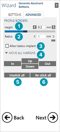
It is recommended not to use the Allow below implant [3] option.
The entire margin can be moved together with the Move all margins [4] buttons.
Click Unstick all [5] to detach all control points of all constructions. All control points and toggle disks switch to green. The opposite can be reached by clicking Re-stick all [6], so that all control points and toggle disks switch to pink.
Force a predefined shape, either by holding the [Shift] key and clicking Unstick all to force a predefined radius, or by holding down [Ctrl] and clicking Unstick all to force a predefined height.
Angulated screw channel
For all screw-retained products, the screw channel [1] is visible throughout the design workflow.
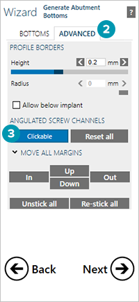
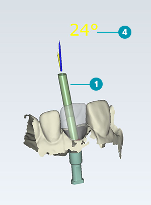
If you are designing a product that allows for an angulated screw channel, manipulate the angulation using the Abutment design wizard or the Generate abutment bottoms wizard under Advanced [2]. Select Clickable [3] and click at the space where you would like the screw channel to exit from the restoration. The angle of the screw channel [4] will be displayed above the design.