Cut view
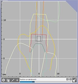
The cut view feature provides advanced methods for displaying sectional views of your design and performing simple measurements.
Click Cut view 
The cut view rectangle moves as the mouse hovers over different objects in the scene.
Click to position the rectangle. As you rotate the 3D view, the cut view moves so you see the 2D and 3D situations from a similar angle. The triangle in the corner of the 2D and 3D images marks the orientation. Once the rectangle is positioned, move it by grabbing it at the corner.
Note
Alternatively, right-click an object in the scene to open the context menu, and select Cut view and then Show cut here.
To close the cut view, click Cut view in the main toolbar (again).
Cut view measurements
The cut view also facilitates measurements.
On the cut view viewer click a start and end point, and the distance between them will be displayed in mm. If you select a start or end point near a line, the arrow becomes green and automatically connects to it. If you select a point in an empty space, the arrow becomes yellow to show that the measurement may not be useful. The arrow becomes red if the measurement lost the object it was previously snapped to (and the measurement will no longer be displayed).
To delete a marker, press Delete while the mouse is near a marker (this is indicated by a circle around the dot).
Note
Always keep in mind that the 2D measurement tool only measures distances in the particular cut plane you have chosen, and not the shortest distance between two surfaces. Thus, measuring a 3D situation in a 2D sectional view is an oversimplification, and such a 2D measurement is prone to misinterpretation. Consider this effect especially when checking minimum thicknesses or minimum clearance. We recommend to use the 3D measurement tool in such situations instead. When the 3D measurement tool is open, it can be used in the cut view viewer as well, and the 2D measurement tool of the cut view will be deactivated.
Repositioning the cut view
Repositioning the cut view
Press [Ctrl] or [Shift] or move the mouse close to the border to show the rotation and movement arrows.
Use the arrows at the cut rectangle edges to move the cut view. Press [Shift] to restrict the movement to the cut plane.
Use the arrows in the middle of the cut rectangle edges to rotate the cut view along the corresponding circle.
Positioning modes
To position the cut view over a specific object, click Set by clicks 
To align the 3D view to your 2D view perspective, click Focus cut main viewer 

Click Reset cut 
Auto-rotation modes
The Cut settings 
Disable auto-rotate cut 
Rotate the cut in 90° steps 
Smoothly rotate the cut 
Navigating in the cut view
Inside the cut view window, you can use the standard mouse functions:
| Mouse function | Action |
| Scroll wheel button | Zoom in and out. This also resizes the cut view rectangle accordingly in the 3D view. Minimum and maximum zoom levels are limited. |
| Ctrl + scroll wheel button | Move the cut along the dental arch in small steps (if the position on dental arch slider is not available, it moves the cut along the cut plane normal). |
| Shift + scroll wheel button | Move the cut along the dental arch in larger steps. |
| Right + left mouse button | Pan the view. |
| Right mouse button | Change the position of the cut view. Move up and down to move the cut along the cut plane normal. Alternatively, use the Position on dental arch slider to navigate through the arch. Move left and right to rotate the view around its vertical axis (if auto-rotation is disabled, the cut can be rotated around the plane normal by pressing the right mouse button near the cut view corners). |
| Right mouse button + Ctrl | Tilt the view. |
| Right mouse button + click | Open the context menu and select an option to zoom to the specific object. |
| Press wheel button | Center the view on the clicked point. |
Visualization modes
The Cut settings 
Visualization mode: Instead of having a pure 2D view (Intersection lines), you can switch to a 3D sectional view (Sectional view). Measurement also works in the sectional view mode.
To hide the grid, clear the Show grid check box.
