Connectors
Connectors will be generated for implant bridge cases.


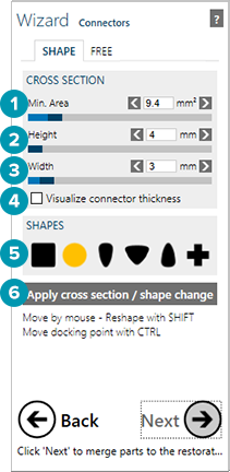
Connectors can be customized in various ways. The minimum size of the connector is defined by the cross-sectional Minimum Area [1], Height [2] and Width [3]. These values can be adjusted above their minimum values using the corresponding sliders. To visualize the thickness of the connectors, click Visualize the connector thickness [4]. You may also switch between different predefined shapes by clicking on Shapes [5]. To apply your changes, click Apply cross section/shape change [6].
Tip
Any changes you make, will be applied to all connectors. To apply different parameters/shapes to specific connectors in the construction, go to expert mode, and use the context menu (right-click on the connector, and select Connectors. Alternatively, customize the connectors using the Free tab, as explained below).
To change its position, drag the connector. It will re-adapt itself to the teeth once you drop it at its new position.
Dragging the connector will change its position on both sides. To change the docking place of the connector only on one side, hold down [Ctrl] and click the tooth to change the position of the docking point [7].
 |
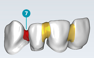
When generating connectors, the software tries to enforce the minimum cross-sectional area, minimum height and width. In some rare cases, this may fail, due to space restrictions. The connector will then be displayed in red. This situation needs manual work to be resolved. Try changing the location of the connector (by dragging it or by repositioning the docking points) or use the connector free-forming as described below. |
Customizing connectors - the Free tab
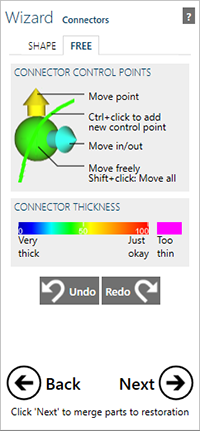
Switch to the Free tab to further customize your connectors or to visualize connector thickness.


Edit connectors by moving control points. When you move the mouse close to one of the control points, it will grow and spawn arrows.
Drag the control point itself for free movement in all directions.
Drag one of the arrows for movement that is restricted to the direction of the arrow.
To insert additional control points, hold down [Ctrl] and click on the green line in the center of the connector, at the location where you would like to insert the new control points. The more control points you add, the more freedom you have in designing complex connectors. To move several control points at once, hold down [Shift] while dragging one of the green control points.
Tip
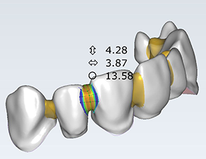
If you design the connector substantially thinner than specified, the software will mark the approximate area which is too thin in magenta. Whenever you see a partially magenta-colored connector, change its shape to make it thicker. If the connector area is violating the minimum size restrictions, you are unable to proceed to the next design step.
 |
Minimum connector values are only checked after the Connector wizard. When the bridge design workflow is completed and the restoration is merged, you have the option in expert mode for additional free-forming the merged design. Note that the minimum connector values are no longer checked here, so it is suggested to stay away from the connectors while using this tool, otherwise you are at risk of designing a construction that may not fall within the constraints |
Arch lengths
For multi-unit restorations, the minimum connector area height and width are a function of the free hanging arch length, or the arch length between implant connections. In the Connectors wizard, you are able to adjust the cross-sectional Minimum Area, Height and Width above their minimum values
Additionally, for bridge extension lengths, or the length of a unit attached to the end of the bridge which is not supported by an implant, the design must not exceed the maximum value specified for the product.
 |
In the software, the minimum connector area, height and width, as well as the maximum extension length are compulsory. Any designs which are violating these values are prevented from proceeding to the next step in the wizard. Again, please note this is not enforced when editing in free-form mode after the design has been merged. |