Model alignment
To align the model with the boundary planes or the pin base:

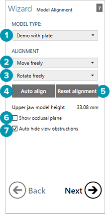
Select the Model type, e.g., "Demo with plate", "Demo without plate", or a vendor-specific preset (e.g., optimized for a certain production system). These are two basic different model fabrication processes.
The model without plate is a process of a solid model with the die(s) being removable from within the main body of the model. This process is a common digital technique. For a model without plate the scans will appear between two parallel planes, representing the boundaries of the model. The green plane should be under the lower jaw, the blue plane should be above the upper jaw.
The model with plate is a premanufactured model base that will accommodate the model, which will be sectioned digitally, very similar to the traditional technique. For a model with plate, the selected pin base will be visualized. Red shading indicates that a section of the scan lies outside the defined planes/plates, while gold indicates the scan data area to be used. The scan data marked in red will be clipped.
To easily position the scans within the model boundary, click Auto align [4].
If the resulting position of the scans is not the intended one, click and drag the scans to freely move them. To freely rotate the scans into the model boundary, right-click and drag. To limit the range of motion use the Move [2] and Rotate [3] drop-down selectors.
Reset alignment [5] will restore the scan to its original position before any motion or rotation was applied.
If there is an antagonist scan, use the slider under Model height or enter a value in this field to adjust the height of the model.
Note
For models without a plate, the minimum height should allow for the minimum pin-size to rest in the base.
For a model "with plate" select Show occlusal plane [6] in order to determine the optimal alignment.
Auto-hide view obstructions [7] uses an algorithm to determine when to hide one or the other arch.