Adjusting the cylinders
Cylinders are designed by dragging their handles in the 3D window, and from setting the various cylinder parameters.
Cylinder design limits
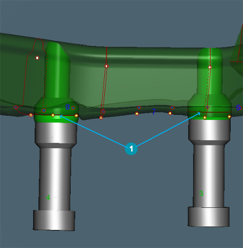
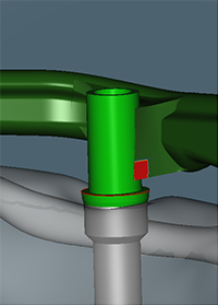
The red lines appearing on the cylinders in the 3D view (visible when turning the 3D model upside down) indicate the limit of the design.
The design of the bar should not exceed the cylinder design limits to make sure the bar does not interfere with the connection between implant and cylinder. If a design exceeds the limits, it will be rejected by production and you will need to adjust the design and reorder. Make sure to never set a bar lower than the red lines [1] on the cylinders. The red lines on the cylinders are milling constraints. In the example below cylinder 3 (on the right-hand side) is placed too low.
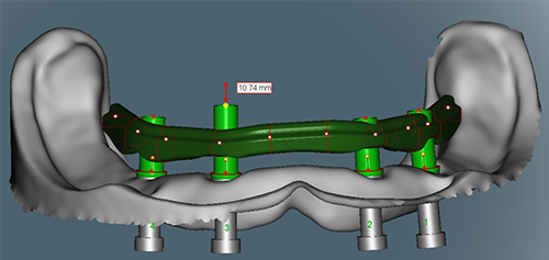
Adjusting the cylinder height
The cylinder height can be adjusted for Round, Dolder, Hader and Montreal with metallic lingual bars.
To adjust the cylinder height:
Double-click the prosthesis in the visibility tool to make it transparent.
Click Unlock ![]() on the Front button.
on the Front button.
Note
For Montreal bars with metallic lingual you must select the Fit cylinders to wax-up option in the Cylinders parameters ![]() to display the cylinder handles.
to display the cylinder handles.
Use the cylinder handles to change the height of the cylinder.
Use the 2D cross-section view to validate the distance between gingival surface and extension.
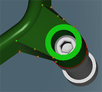
Link to offset cylinder
Some designs may require to offset cylinders from the bar body. Links unite these offset cylinders to the bar. The link is generated as the bar is offset from the cylinder.
Links may be used with Dolder, Free-form milled, Wrap-around and Hybrid bars.
Adjusting the link to the offset cylinder
To adjust the link to the offset cylinder:
Click the link of the offset cylinder.
In the Cylinders parameters ![]() , make sure that Show links is selected.
, make sure that Show links is selected.
Click the link to edit. The link handles are displayed.
Move the handles individually as necessary. Alternatively, click Rebuild link to obtain a new link proposal.
Notes
The link handles situated on the bar can be moved in pairs when the Link handles lock mode option is selected.
The milling constraint for a link is at a minimum of 2.5 mm in height. The link should be as tall as or taller than the height of the bar. Red highlighting around the link may appear if constraints are undersized. On clicking the link, red lines between handle pairs may appear, meaning that a height constraint was not respected. In the same manner, a red zone may be shown on the link, near the cylinder, meaning that the minimal distance (milling constraint) between the link and the cylinder base was not respected. A warning message will be displayed when saving the bar in such cases.
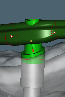
Modifying the upper collar height of the cylinder
This option is available for Wrap-around and Hybrid bars.
This procedure is optional and should be required only for particular situations.
Click Front.
Click the cylinder to display the cylinder collar.
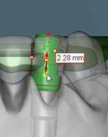
Drag the lower red handle located near the collar. A red arrow and the height of the collar is displayed.
Notes
The height is measured from the bottom of the cylinder.
The collar cannot be set lower than the red line.
Rotate the model to validate the position of the collar.
The upper collar height is set to the selected position.
Note
The upper height of the collar can also be modified from the Cylinders parameters ![]() .
.
Tilting the cylinder collar
This option is available for Wrap-around bars only.
Notes
This procedure is optional and should be required only for particular situations.
The modification of the upper height of the cylinder collar step must be completed.
Hide or display the prosthesis and make the model transparent to facilitate viewing.
Set the values of the collar's diameter, upper height and lower height from the Cylinders parameters ![]() .
.
Click the cylinder.
Rotate the cylinder to view the position of the collar.
Drag the upper red handle located near the collar. A red arrow will be displayed.
Rotate the model to validate the position of the collar in relation to the tissue contours.
The collar is set to the selected position.