3D data editor
Edit the model area, if necessary.

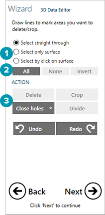
Prior to the editing action, select the surface(s) [1] to be affected by the outline you draw:
Select straight through to highlight all surfaces, even those hidden behind the visible surface.
Select only surface to highlight only the visible surface(s) and ignore any surfaces hidden behind.
Select by click on surface to choose one of many overlapping surfaces.
In the CAD viewer, select areas of the scan by clicking points to highlight area(s) of the scan you want to edit. Double-click the last point to complete the outline. Or, define selections globally [2] without drawing an outline:
All to highlight all surfaces of the scan.
None to clear all existing selections.
Invert to reverse the highlighted and non-highlighted regions of the scan.
Click one of the actions [3]:
Delete to remove all of the highlighted surfaces.
Crop to remove all of the non-highlighted surfaces, preserving only the highlighted surface.
Close holes to look for completely highlighted holes, and close them with artificially generated surfaces, interpolated from surrounding edges. Hold down the arrow next to Close holes and select Size threshold. Use the slider or enter a value to adjust the size of the threshold. Note: This data is not actual scan data, and should not be used when an intimate fit is desired.
Divide to separate each area of highlighted scan data into a separate surface
If there is an antagonist scan, select Repair scan data intersections to visualize the antagonist scan intersections. Click Repair to fix the intersections.